Gear Pumps Pumping System
Reversible equipment
Working principle
A gear pump produces flow by carrying fluid in between the teeth of two meshing gears. One gear is driven by the drive shaft and turns the idler gear. The chambers formed between adjacent gear teeth are enclosed by the pump housing and side plates (also called wear or pressure plates). A partial vacuum is created at the pump inlet as the gear teeth unmesh. Fluid flows in to fill the space and is carried around the outside of the gears. As the teeth mesh again at the outlet end, the fluid is forced out.

Description and operation
This equipment receives the additive from a tank and drives it to a measuring glass, then the pump draws the additive from the measuring glass and drives it to the concrete admixture. The assembly has a pressure controlled valve operated by a solenoid valve and a filter preasure regulator to control the flow of the additive at the inlet. Through the outlet pipe this flow is controlled by a flow meter.
Moreover, it’s equipped with three check valves in order to prevent the backflow.
Everything is integrated within a polyethylene box to protect it against external agents.
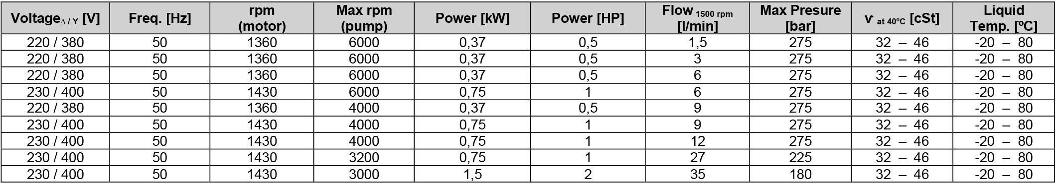
Operating data
Dimensions (mm)